Wednesday, December 8, 2010

HOW TO USE CONDENSER MIC OR ECM

Description:
This page describes how to use or connect and use 2 and 3 terminal electret condenser microphones (ECM's). The bottom section shows the connections and how to substitute from one type to another.


Mic Inserts
Viewed from above all mic inserts look similar to the left image. ECM inserts can be bought quite cheaply from many electronics outlets, and offer high quality sound output. They can also be salvaged from old cassette players and radio-cassettes. An ECM contains a very sensitive electret type microphone (high output impedance) and an integral FET amplifier. The amplifier stage buffers the high output impedance of the mic and boosts an average speech signal to around 1 to 2mV when spoken about one metre away from the mic insert.


Two Terminal Type ECM The ground or common connection of a two terminal ECM insert can be identified as the solder connection that is touching the case or body of the mic,


Three Terminal Type ECM
With a three terminal ECM, the ground or common connection will be touching the case or body, the other two contacts will be the audio output and power pins


Connecting 2 and 3 terminal ECM's

The schematic symbol for a 3 terminal ECM insert is shown on the left diagram. It has separate power, common, and signal outputs. The schematic symbol for a 2 terminal ECM insert is shown on the right diagram. To use a 2 terminal ECM, the signal output is connected to the power terminal, fed via a current limiting resistor, (typical value 1k or 2k2). The signal output therefore has a DC component which must be removed before connecting to an amplifier. This is achieved with an output capacitor connected to the power terminal of the ECM, a typical value being 1-10uF.


Sunday, September 5, 2010

ZOBEL NETWORK FOR LOUDSPEAKER


Before we go in to our discussion of" zobel network compensation for loudspeaker", we shall have a brief look over internal structure of loudspeaker and what a voice coil is...

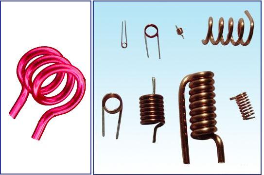
A loudspeaker is an electroacoustic transducer that converts an electricalsignal in to sound ,The voice coil moves in accordance with the variations of an electrical signal and causes sound waves to propagate through a medium.fig1 shows the internal structure of speaker and fig2 a voice coil!!
WORKING :
1.voice coil is a copper winding which becomes an electromagnet when current is passed through it.
2.if a time varying current(a.c signal) is passed it magnetises and demagnatises according to current variation.
3.the voice coil is concentrically placed in a permanent electromagnet.
4.when the coil is electromagnetised by current,then coil tends outward due to repulsive force of permanent magnet and voice coil.
5.when coil is demagnetised it rests in original position,likewise the coil moves producing sound that is varying according to the applied signal and hence it reproduces the voice or music.
now we enter in to the present article of"ZOBEL NETWORK"!!!
Zobel networks are a type of filter section based on the imageimpedance design principle. They are named after "Ottozobel" of Bell labs who published a much referenced paper on image filters in 1923.
as voice coil is a copper wound coil this behaves as an inductor which offers impedance at high frequencies.we know that at high frequencies the inductor blocks ac,in a similar way the loudspeaker blocks ac components and exhibit high impedance.so that the impedance characteristics are nonuniform at all frequencies. THE LOUDSPEAKER IMPEDANCE IS INDUCTIVE AT HIGH FREQUENCIES(unusual from being resistive).
DESIGNING ZOBEL NETWORK: we can design,If the voice coil inductance is known, then a suitable value of capacitance may be calculated quite readily. The first thing to determine is that frequency where the inductive reactance is equal to the DC resistance of the voice coil ...

f = Rvc / ( 2 π Lvc )
Where ...
f = frequency
Rvc = Resistance of voice coil
Lvc = Inductance of voice coil
Once this figure is found, it is a simple matter to calculate the capacitance for the Zobel network ...
C = 1 / ( 2 π f Rvc )
Using the simulated speaker above as an example, we already know that Rvc is 6.2 ohms, so ...
f = 6.2 / ( 2 * π * 1.5-3 ) = 658Hz
C = 1 / ( 2 * π * 658 * 6.2 ) =39uF
we can safely assume that the formula works, and is easy enough to use. The resistance will nearly
always be approximately equal to the voice coil resistance - in some cases it may be found that a small variation is needed, but this is unlikely to be significant.
capacitor can be a bipolar electrolytic could be used, the main problem with bipolars is that they are not stable over time. I recommend that polyester, polypropylene or oil filled paper cap be used.
DISADVANTAGE:The Zobel network will flatten the impedance of the speaker, but at the cost of power dissipation, and a slightly lower than expected overall impedance. Naturally, the power dissipated by the resistor is turned into heat, not sound, reducing effective efficiency. The lower impedance may cause some stress to certain amplifiers, but most should be able to cope with the slight extra loading!!

Sunday, August 29, 2010

How to make an INDUCTOR

My discussion here is very simple,unlike presenting u all the history like Wikipedia. and boring you with all its properties characteristics etc. i shall leave here a simple discussion which is very much needed practically when you work them.the main emphasis here is about HOW TO DESIGN AN INDUCTOR and its COLOR CODES!!!

Sometimes you may be unable to find a particular inductor the market. This is actually a problem faced by most of the electronic hobbyists and the problem becomes more serious if your project is RF related. The inductors required for RF circuits (antenna, tuner, amplifier etc) are almost impossible to find in the market and the only solution is nothing other than home-brewing them.

how to make an air cored inductor

often designing inductor,we generally go with solenoid which is best suited and easy made.

With a little practice and patience you can construct almost all air cored inductors at home. The inductance of an air cored inductor can be represented using the simplified formula shown below and to calculate the inductance of an air-core inductor, the same equation may be used.


L = [d2 n2] / [18d + 40l] (approximate formula)
Where’ L ‘ is the inductance in Micro Henries [µH]
  • ‘d’ is the diameter of the coil from one wire centre to another wire centre. It should be specifies in inches.
  • ‘l’ is the length of the coil specified in inches.
  • ‘n’ is the number of turns.

Notes :

  • The length of the coil used in the inductor should be equal to or 0.4 times the diameter of the coil.
  • As shown in the equation, inductance of the air-core inductor varies as the square of the number of turns. Thus the value ‘l’ is multiplied four times if the value of ‘n’ is doubled. The value of ‘l’ is multiplied by two if the value of ‘n’ is increased up to 40%.

Winding the coil.

  • The coil must be first wounded on a plastic former of the adequate diameter (equal to the required core diameter).
  • The winding must be tight and adjacent turns must be as close as possible.
  • After the winding is complete, slowly withdraw the core without disturbing the coil.
  • Now apply a thin layer of epoxy over the coil surface for mechanical support.
  • Remove the insulation from the coil ends.

Example

Suppose you want to make an inductor which produces an inductance of 10 μH. The diameter of the coil is 1 inch and the coil length is given by 1.25 inches. You will have to find the number of turns of the coil.

Thus substituting the values in the above equation t

L = 10 inches

d = 1inch

l = 1.25 inches

n = √{L [18d * 40l]} / d = 26

Thus, the number of turns of the coil will be 26.

Number of turns/inch = 20.8

NOTE:for guys designing fm transmitters first wind 8-10 turns on a pencil (whose diameter 1/4 inches is just enough to produce required inductance for fm band).the wire may be 24 swg.for more details just mail i will provide u the details!!

those guys who cant do all these just try the softwares RFCALC or RFSIM99(links given below) this would really help you out.these softwares readily calculate and give you the dimensions you must wind,to get required inductance values.

http://electroschematics.com/835/rfsim99-download/
http://sourceforge.net/projects/rfcalc/
while using these softwares you need inches to millimeter conversion some times,when circuit needed dimensions are specified in mm for that just calculate using standard conversion

SOURCE:www.circuitstoday.com&www.elexp.com

Thursday, August 26, 2010

HOW TO USE CONDENSER MIC OR ECM

Description:
This page describes how to use or connect and use 2 and 3 terminal electret condenser microphones (ECM's). The bottom section shows the connections and how to substitute from one type to another.


Mic Inserts
Viewed from above all mic inserts look similar to the left image. ECM inserts can be bought quite cheaply from many electronics outlets, and offer high quality sound output. They can also be salvaged from old cassette players and radio-cassettes. An ECM contains a very sensitive electret type microphone (high output impedance) and an integral FET amplifier. The amplifier stage buffers the high output impedance of the mic and boosts an average speech signal to around 1 to 2mV when spoken about one metre away from the mic insert.


Two Terminal Type ECM The ground or common connection of a two terminal ECM insert can be identified as the solder connection that is touching the case or body of the mic,


Three Terminal Type ECM
With a three terminal ECM, the ground or common connection will be touching the case or body, the other two contacts will be the audio output and power pins


Connecting 2 and 3 terminal ECM's

The schematic symbol for a 3 terminal ECM insert is shown on the left diagram. It has separate power, common, and signal outputs. The schematic symbol for a 2 terminal ECM insert is shown on the right diagram. To use a 2 terminal ECM, the signal output is connected to the power terminal, fed via a current limiting resistor, (typical value 1k or 2k2). The signal output therefore has a DC component which must be removed before connecting to an amplifier. This is achieved with an output capacitor connected to the power terminal of the ECM, a typical value being 1-10uF.


Sunday, August 22, 2010

RESISTORS

RESISTOR COLOR CODES:

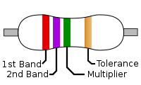
fig:1

A diagram of a resistor, with four color bands A, B, C, D from left to right A diagram of a 2.7 MΩ color-coded resistor.

Resistor values are always coded in ohms ( symbol Ω), capacitors in picofarads (pF), and inductors in microhenries (µH).

  • band A is first significant figure of component value
  • band B is the second significant figure
  • band C is the decimal multiplier
  • band D if present, indicates tolerance of value in percent (no color means 20%)


how to calculate:

1# always start from opposite end of tolerance band

2#calculate by formula

resistance value :color1 color2 X 10(power color3)

3#(optional) finally to that value add this tolerance

+/- (5/100)*R(for gold)

+/-(10/100)*R(for silver)

+/-(20/100)*R(no color)

let us make this a little clear with an example take example as fig:1

1st color is red means '2'

2nd color is violet means '7'

3rd color is green means '5'(multiplier)

4th color is tolerance i.e gold here

resistance value is: 27x10(power)5

i.e 2700000=2.7 mega ohms

for accurate value add tolerances also

i.e 2.7M +/- (5/100)*2.7M

2.7M+/- 135000

so the resistance may vary from 2835000 to 2565000 ohms


Resistors manufactured for military use may also include a fifth band which indicates component failure rate

Tight tolerance resistors may have three bands for significant figures rather than two, and/or an additional band indicating temperature cofficient, in units of ppm/k.

All coded components will have at least two value bands and a multiplier; other bands are optional

The standard color code per EN 60062:2005 is as follows:

Color Significant
figures
Multiplier Tolerance Temp. Coefficient (ppm/K)
Black 0 ×100 250 U
Brown 1 ×101 ±1% F 100 S
Red 2 ×10² ±2% G 50 R
Orange 3 ×10³ 15 P
Yellow 4 ×10⁴ 25 Q
Green 5 ×10⁵ ±0.5% D 20 Z
Blue 6 ×10⁶ ±0.25% C 10 Z
Violet 7 ×10⁷ ±0.1% B 5 M
Gray 8 ×10⁸ ±0.05% A 1 K
White 9 ×10⁹
Gold ×10-1 ±5% J
Silver ×10-2 ±10% K
None ±20% M

  1. Any temperature coefficent not assigned its own letter shall be markd "Z", and the coefficient found in other documentation.
  2. For more information, see EN 60062

example2#:

As an example, let us take a resistor which (read left to right) displays the colors yellow, violet, yellow, brown. We take the first two bands as the value, giving us 4, 7. Then the third band, another yellow, gives us the multiplier 104. Our total value is then 47 x 104 Ω, totalling 470,000 Ω or 470 kΩ. Our brown is then a tolerance of ±1%.

Resistors use specific values, which are determined by their tolerance. These values repeat for every order of magnitude; 6.8, 68, 680, and so forth. This is useful because the digits, and hence the first two or three stripes, will always be similar patterns of colors, which make them easier to understand.

There are many mnemonics to remember the color code here are some of them :

Black Brown Red Orange Yellow Green Blue Violet Gray White

B. B. R O Y of Great Britain has Very Good Wife.
Bill Brown Realized Only Yesterday Good Boys Value Good Work
Bak B R O, Yeah Greasy Blubber's Very Grabable, Why?
Bad Boys Run Our Young Girls Behind VictoryGarden Walls.
Big Boys Race Our Young girls But Violet Generally Wins
Bye Bye Rosie Off You Go Bristol Via Great Western
Big Brown Rabbits Often Yield Great Big Vocal Groans When
Bye Bye Rosie Off You Go Birmingham Via Great Western

thanks to thanujakothamasu for reminding me this mnemonics

VARIABLE RESISTANCES:


variable resistor track and wiper variable resistor
Variable resistors consist of a resistance track with connections at both ends and a wiper which moves along the track as you turn the spindle. The track may be made from carbon, cermet (ceramic and metal mixture) or a coil of wire (for low resistances). The track is usually rotary but straight track versions, usually called sliders, are also available.

Variable resistors may be used as a rheostat with two connections (the wiper and just one end of the track) or as a potentiometer with all three connections in use. Miniature versions called presets are made for setting up circuits which will not require further adjustment.

Variable resistors are often called potentiometers in books and catalogues. They are specified by their maximum resistance, linear or logarithmic track, and their physical size. The standard spindle diameter is 6mm.

The resistance and type of track are marked on the body:
4K7 LIN means 4.7 kohm linear track.
1M LOG means 1 Mohm logarithmic track.

Some variable resistors are designed to be mounted directly on the circuit board, but most are for mounting through a hole drilled in the case containing the circuit with stranded wire connecting their terminals to the circuit board.


Linear (LIN) and Logarithmic (LOG) tracks

Linear (LIN) track means that the resistance changes at a constant rate as you move the wiper. This is the standard arrangement and you should assume this type is required if a project does not specify the type of track. Presets always have linear tracks.

Logarithmic (LOG) track means that the resistance changes slowly at one end of the track and rapidly at the other end, so halfway along the track is not half the total resistance! This arrangement is used for volume (loudness) controls because the human ear has a logarithmic response to loudness so fine control (slow change) is required at low volumes and coarser control (rapid change) at high volumes. It is important to connect the ends of the track the correct way round, if you find that turning the spindle increases the volume rapidly followed by little further change you should swap the connections to the ends of the track.


Rheostat

rheostat symbol
Rheostat Symbol
This is the simplest way of using a variable resistor. Two terminals are used: one connected to an end of the track, the other to the moveable wiper. Turning the spindle changes the resistance between the two terminals from zero up to the maximum resistance.

Rheostats are often used to vary current, for example to control the brightness of a lamp or the rate at which a capacitor charges.

If the rheostat is mounted on a printed circuit board you may find that all three terminals are connected! However, one of them will be linked to the wiper terminal. This improves the mechanical strength of the mounting but it serves no function electrically.


Potentiometer

potentiometer symbol
Potentiometer Symbol
Variable resistors used as potentiometers have all three terminals connected.

This arrangement is normally used to vary voltage, for example to set the switching point of a circuit with a sensor, or control the volume (loudness) in an amplifier circuit. If the terminals at the ends of the track are connected across the power supply then the wiper terminal will provide a voltage which can be varied from zero up to the maximum of the supply.


Presets

preset symbol
Preset Symbol
These are miniature versions of the standard variable resistor. They are designed to be mounted directly onto the circuit board and adjusted only when the circuit is built. For example to set the frequency of an alarm tone or the sensitivity of a light-sensitive circuit. A small screwdriver or similar tool is required to adjust presets.

Presets are much cheaper than standard variable resistors so they are sometimes used in projects where a standard variable resistor would normally be used.

Multiturn presets are used where very precise adjustments must be made. The screw must be turned many times (10+) to move the slider from one end of the track to the other, giving very fine control.

preset presets multiturn preset
Preset
(open style)
Presets
(closed style)
Multiturn preset

GENERALLY ALL VALUES OF RESISTANCES ARE NOT AVAILABLE DO U KNOW WHY???

different people say different reasons for this but my reason is very straight..

i think this is reason!!!

1k resistor is available but 500 ohm resistor is not available, this is from the fact that 500 ohms can be obtained

from connecting two 1k 's

i shall make my point little bit clear with another example 2.2k and 2.7k are available but why 2k is not available???

because it can be obtained by connecting two 1k's in series

not believing my words!!!! come on just check out by taking different examples and assess ur self!

*Resistors are available for different power levels:

like 0.25w,0.5w,1w,2w,5w etc based on the circuitry demand and application each of them are preferred!!

*Resistors are the contributors of NOISE in communication systems

NOISE can be two types in a communication system

1.external noise (due to transmission medium)

2.internal noise(due to resistance)

internal noise is produced by resistors which is also called THERMAL NOISE or WHITE NOISE

or JHONSONS NOISE

this noise is the random noise generated in a resistor or a resistive component of a complex impedance due to rapid and random motion of molecules,atoms and electrons

according to kinetic theory of thermodynamics the temperature of a particle denotes its internal kinetic energy. this means that the temperature of the body expresses the rms value of velocity of motion of particles in body. as per this theory kinetic energy of particles become apprx zero(zero velocity) at absolute zero.

therefore noise power produced in the resistor proportional to absolute temperature and also

the noise power is prop to bandwidth over which noise is measured

therefore expression for maximum noise power output of a resistor may be given as

p=kTB

where 'k' is boltzmann's constant

'T' is absolute temperature

'B' is bandwidth in hz