Friday, August 19, 2011

HYPER TERMINAL TEST FOR TROUBLE SHOOTING RS-232(serial port)

Hi friends, are you struck with problems when using serial port during programming micro controllers like getting error message"no response from from micro controller" ???or you have trouble in interfacing computer with external slave processor like micro controller to transfer
data between them.then you are at the right place.
In this tutorial i will give you the way how we troubleshoot the serial port.by troubleshooting you can find out whether your serial port is working properly or not.The method used for this known as "HYPER TERMINAL TEST".

This is how a serial port(DB-9) looks like,shown below:


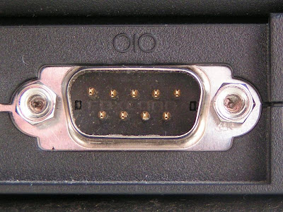
Pin 2--->data receive
Pin 3--->data transmit
Pin 5---> GND

Step1:
-------
Short the pins 2 and 3 as shown in the figure.

Step2:
-------
Now go to start menu in your PC

Start Menu--->All programms--->Accessories--->Communications--->Hyper Terminal

Step3:
-------
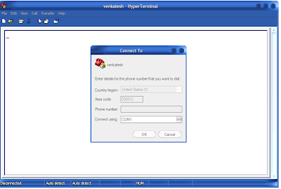
When you click hyper terminal,you will get a window as shown in the snap below
enter some name to the connection (i named it "venkatesh") and click 'ok'.

Step4:
------
you get a window prompting you to enter location
enter some location and pincode.
select 'connect using' as COM1 and click 'ok'

Step5:
-------
Then you get a window shown below,with small window "com1" settings
select
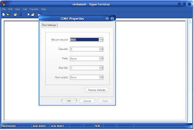
bits persecond as "9600"
data bits as "8"
parity as "none"
stop bits as "1"
and flow control as "none"
Now click "apply" and "ok"
Step6:
-------
A blank window appears as shown below with cursor blinking.

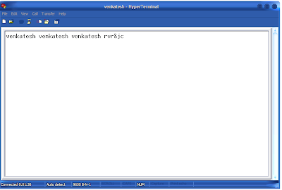
keep shorting the pins 2 and 3,type some text with the keyboard
Now , if you can see the text you typed on the window.
then it means that there is no problem with your serial port and every thing is correct with
the PC,if not there is some thing wrong with the PC serial port.
Hence your serial port is TESTED.

Up to this point i have just told you the process to trouble shoot the serial port but didn't tell you
the logic behind what we did actually.
what is the logic behind this hyperterminal test?????

generally
1.whatever input we give from the keyboard,it comes out through the serial port pin 3.
2.and whatever input we get from the serial port pin2,we can display that in hyper terminal
using the above settings.
so keeping this as basis just come back to what we did,we shorted the pins 2 and 3.
by that,what we type in the keyboard is sent to pin3 first and then back to pin2(as they are shorted),so the characters typed by us on the keyboard are displayed back to us:)

Hope you enjoyed the tutorial,for any queries and comments,just post them here or to my mail
have a good day bye:)
--Regards
Venkatesh

Friday, August 5, 2011

89V51XX PROGRAMMER USING SERIAL PORT

89v51xx series are very special series of microcontrollers in 8051 family as
they are dead easy to burn and these microcontrollers have more flash memory
compared to 89s series and 89c series.
these microcontrollers are manufactured by NXP(founded by philips).
they are boon to the beginners who dont have a parallel port and cannot make
89sxx serial programmer,as microcontrollers are "IN SYSTEM PROGRAMMABLE"(ISP)
these micro controllers have ISP through UART.which means that,it requires only one level conversion MAX232 ic between the computer serial port and the microcontroller.more
the burning process is carried out only by two pins TXD(transmit) and
RXD(receive).and the program is burned to FLASH ROM via UART through these
pins.
89v51RD2 programmer circuit:

click on image to enlarge


89v51rx2.h headerfile download for keil IDE programming in 'c'
software tools:
After the circuit is connected as shown in the above schematic,we should use
a software to send the program bits(burn) in to the microcontrollers FLASH ROM
the software specially dedicated for this philips microcontrollers is
called "FLASH MAGIC".
detailed step by step procedure is given with snapshots below.
step1:
------
select the device name,am using 89v51RD2 here as an example.
step2:
------
select com port as com1 and make sure that no other peripherals are connected
to com port.
step3:
-----
select moderate baud rate,choose minimum while you work for the first time
later you can increase to optimum,by increasing step by step.
step4:
------
select interface as none(isp).
step5:
------
browse for the .hex file to be burned to the microcontroller.

step6:
------
now click start buttton,this starts burning process.
step7:
------
the burning status is shown in the bar.
step8:
------
when the burning process is finished,you get the "finish" message.
now your device is programmed successfully!!!!
so enjoy!!!!:)

EXTRA READING:
--------------
1.some microcontrollers which support this method are 89v51RD2,89v51RB2,
89v51Rc2,89v52x2,89v660,89v662,89v664....etc.
2.you can remove the connection between the RESET and DTR and manually make
RESET high immediatly when the software is ready to start programming.
3.in the circuit given above,the RESET is connected to the DTR pin of serial
port,this takes care of making the RESET high during the burning process.
meaning whenever serial port is ready to burn ,it asserts DTR
(data terminal ready)pin(pin4 of DB-9)and hence making the RESET to go high.
4.one more speciality is that these microcontrollers can also be burnt
through parallelport method given in my previous tutorial.
5.if any program changes are made,the .hex file is automatically updated,no need
to select it again.

****any queries or comments ??? just post them here,or mail me,Thank you!!!!!!!!**********
-Regards
venkatesh

89SXX PARALLEL PORT PROGRAMMER USING LPT1

After we develop a program,we need to burn the .hex code file generated by c compiler in to the micro controller,for this we need some hardware that must be connected between the computer and the microcontroller.
The hardware is known as programmer or burner.there are different to burn the
program in to the EEPROM of the micro controller.
parallel port method(using LPT1):

click on image to enlarge


This method uses parallel port(LPT1)(DB-25)also called printer port,of computer
to burn the program.
and is very simple programming method has only 5 connections.
note:this parallel port programmer can be used to burn the microcontrollers
like 89s51 or 89s52. that is microcontrollers which has "IN SYSTEM PROGRAMMING"
(ISP) facility.
SOFTWARE TOOLS :
After the circuit is connected as shown in the above schematic,we should use
a software to fuse bits in to the EEPROM of microcontroller,the software i used
here is "ISP-Flashprogrammer 3.0a".install this software and u can see this window,
step by step procedure is shown below
step1:
------
The window shown in the snapshot appears as you open the software,browse the
.hex file to be burnt to the microcontroller,by clicking "open file".
step2:
------
now select the device to be programmed,we are using here 89s52 so select it.
step3:
------
now click "write",the status bar appears which indicates the status of
burning process.and as soon as the device is programmed.you will get a message
"programmed succesfully"
now your device is programmed successfully!!!!
so enjoy!!!!:)


EXTRA READING:
--------------
1.the microcontrollers which have ISP facility can only be programmed by this
method.
2.microcontrollers having ISP facility can be idetified by 's' in their name;
's' means in "system" programmable.
for example 89s52 in this name 's' indicates that this microcontroller is
having ISP facility and hence parallel port method can be used.
3.this method can be used to burn AVR family of microcontrollers also.
4.we can generalise that any microcontrollers which have MISO,MOSI,SCK pins
can be programmed through this method.
5.MISO is master in slave out,pin which takes bits in to master processor(PC)that
are given out by slave processor(microcontroller).
MOSI master out slave in,pin which gives bits out of master processor(PC) to
slave processor(microcontroller).
SCK pin is for the synchronisation of clock between master and slave.
6.all computers dont have parallelport,this is motherboard dependent and
most of old motherboards have parallelports where as new systems doesnt.
7.very important thing to be noted is converters like USB to PARALLELPORT converter
,or SERIAL to PARALLELPORT converters dont work.
ISP softwares send the program bits directly to the inbuilt parallelports only.
8.also dont use PCI peripheral interfaces they are waste of time and money,they
wont work for parallelport method.so the thing is parallelport must be originally of
mother board only.
9.no need to make any settings for selecting the parallelport,the software
automatically sends bits to the lpt1.
10.you can also use lock bit combinations to secure your program code.
*****any queries or comments ??? just post them here,or mail me,Thank you!!!!!!!!**********
-Regards
venkatesh

MINIMUM MICRO CONTROLLER CONNECTIONS

A microcontroller is not alone in a circuit,it must be having supporting
components to make it functional.
1.a crystal(12MHZ)and two capacitors(33pF).
2.RESET connection(RC circuit).
3.EA pin connected HIGH to Vcc(only when internal memory is used).
so the minimum microcontroller configuration is as shown in the schematic
below.

MINIMUM MICROCONTROLLER CONFIGURATION:

click on image to enlarge

note:keep this circuit in your memory we will encounter this minimum
configuration very often in our circuits.
EXTRA READING:
1.33pF capacitors are needed to remove unwanted ripple and stray oscillations.
2.crystal is needed to provide oscillations,which moves the instructions to
be executed by the CPU of microcontroller.greater is the crystal speed,
speeder the operation.generally a crystal of 12MHZ to
20MHZ can be used.it can be even high and is limited by microcontroller
fabrication.
3.RESET connection has RC elements which have characteristics of RC highpass
circuit.
4.when microcontroller is powered ON,the RC circuit generates a spike
(a triggering pulse)which makes RESET pin(9) logic'1' for small duration of
time.
when RESET is made high the microcontroller will reset and terminates
all acivities,and the program counter will point to
the first instruction of the program(0000 location of ROM) also all the
values in the registers will be lost.
5.each and every time the supply is switched ON the microcontoller RESETS with
this RC circuit.
6.in order for the RESET to be effective,it must have a minimum duration
of 2 machine cycles(2x12 crystal cycles)i.e 2x1.085uSec.so it must be high
for a minimum of 2 machine cycles before it goes low.
we discuss more about this machine cycles later.
7.a RC circuit with R=8.2k and C=10uF are used here in the circuit,which is
tested and gives our minimum duration of time for which the RESET must be high.
8.most of the 8051 family microcontrollers come with on chip ROM(EEPROM flash)
to store the programs.if the program is accesed from the internal ROM of micro
controller,then the EA pin is tied HIGH to Vcc.for family members such as
8031 there is no on chip ROM and the code is fetched from external ROM.
therefore for 8031 type the EA pin must be connected to LOW(GND),to indicate that
code is stored externally.EA stands for external access(pin 31).it is an input
pin and is connected to Vcc(for internal code access) or to GND(for external
access).it must not be left unconnected(floating).
*****any queries or comments ??? just post them here,or mail me,Thank you!!!!!!!!**********
-Regards
venkatesh

MICROCONTROLLERS POWER SUPPLY

Any microcontroller needs a powersupply to work,the supply must give constant
a constant output voltage.for all our microcontrollers we need a 5V supply.her
e is a simple circuit which gives a regulated supply voltage.and we constantly
use this in our every microcontroller project.

click on image to enlarge

EXTRA READING:
1.prefer to use 1Amp trasformer,as many can be connected to the single supply.
2.you can also half wave rectifier instead of a bridge rectifier,just modify
the rectification section.
3.a 7805 ic used here gives out a constant supply of 5V
4.the capacitors used there are for smoothening and
avoiding unwanted ripple.

89SXX ISP PROGRAMMER USING SERIAL PORT(COM1)

Generally parallel port method is preferred as it is very easy,but
what if we don't have a parallel port for our computer??
so the alternative is serial port programmer.
serial port programmer method uses serial port(DB-9)(com1).
This programmer is a bit complex circuit to construct compared to parallel port method.


89sxx serial programmer circuit:
click on image to enlarge


SOFTWARE TOOLS:

After the circuit is connected as shown in the above schematic,we should use
a software to fuse bits in to the EEPROM of microcontroller,the software i used
here is "ISP_PROG v1.4".install this software and u can see this window.

step1:
------
Now go to options menu and select
settings option,you will get a window asking you to set the com.
as we are using serial port,we select the option com1.and click "ok".


step2:
------


again go to options menu you can see select device option click it,you get
a select device window.select the device as 89s52,as we are using this micro
controller here.and then click "ok".
step3:
------


now select "write device" option and click "RUN" you can now see the status
of the burning of the device.
when the burning process is finished,you get the "finish" message.
now your device is programmed successfully!!!!
so enjoy!!!!:)


EXTRA READING:
---------------------
1.in this method the microcontroller cannot directly communicate with the serial
port of computer it communicates via another slave micro controller.
2.the slave micro controller used between the target microcontroller is pre-programmed
with a boot loader program,this program facilitates programming the micro via serial port.
more on boot loader here.
3.you can see in the figure the first microcontroller is connected to the serial
port of computer through MAX232.the serial port voltage
levels are incompatible with microcontroller voltage levels(TTL).
more about level conversion in my previous tutorial IC MAX232 FOR INTERFACING RS232
so this ic level converts between the serial port and the microcontroller.

4.The 89c2051 again uses a parallelport method to burn code in to it.
5.here the capacitors used around the MAX232 ic are used for clamping the
voltage levels.
6.if your computer dont even have this serial port(laptops dont have serialports),
no problem as every computer now a days have a USB connection,you can use a USB
to SERIAL PORT converter.
7.before using the USB to serial port converter,dont forget to install
USB to serial port drivers.otherwise the device wont be detected at all.
8.if the programmer doesnt work dont panic,there is an easy way of troubleshooting
the serial port,which is discussed in troubleshooting the serialport tutorial.
*****any queries or comments ??? just post them here,or mail me,Thank you!!!!!!!!**********
-Regards
venkatesh